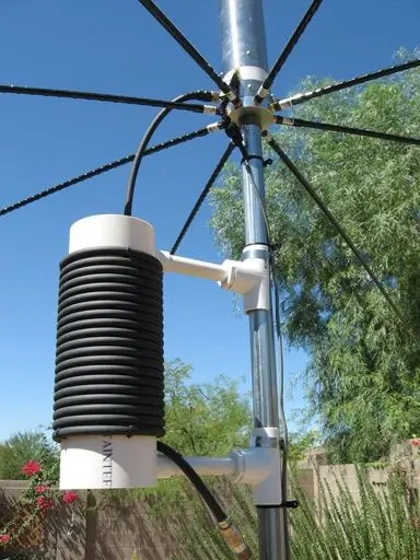
An ugly balun (air-core coaxial choke) is a simple and effective way to suppress common-mode currents on the feedline of your HF antenna. It consists of several turns of coax wound tightly on a non-conductive form such as a PVC pipe or even a soda can.
This calculator helps you quickly design your own ugly balun. Just select the coax type (e.g., RG-58, H-155, RG-8X, LMR-240, RG-213, LMR-400), choose a form diameter (PVC, soda can, or custom), and enter your target frequency. The tool will then:
-
Calculate the required number of turns and coax length
-
Estimate the effective impedance (Zcm) at the design frequency
-
Show how well the choke performs across the major HF amateur bands (80–6 m)
Use this as a practical guideline when winding your own balun. Real-world performance may vary depending on winding tightness, cable quality, and nearby conductive objects.
What is an ugly balun and why it matters
An ugly balun, often referred to as a coax choke or air-wound choke, is a straightforward but highly effective device that helps control common-mode currents on a coaxial feedline. Its unusual name comes from the fact that it is essentially just a coil of coax wound around a non-conductive form, but despite its “ugly” appearance, it plays a critical role in many amateur radio stations.
Without a choke, RF currents can travel on the outside of the coax shield. This can lead to RF in the shack, distortion of antenna radiation patterns, unpredictable SWR behavior, and interference with nearby electronics. By adding a properly sized ugly balun at the feedpoint or near the radio, these unwanted currents are suppressed, resulting in cleaner, more efficient operation.
How an ugly balun works
The ugly balun works by creating inductive reactance to common-mode currents. When coax is wound into multiple turns, the inductance increases proportionally to the square of the number of turns. The higher the inductance, the greater the impedance to currents flowing on the outside of the shield.
For the differential mode signal (the intended RF inside the coax), the ugly balun does almost nothing, since the currents inside the coax are balanced. But for unwanted RF on the shield, the balun acts like a roadblock, ensuring that the feedline does not become part of the antenna system.
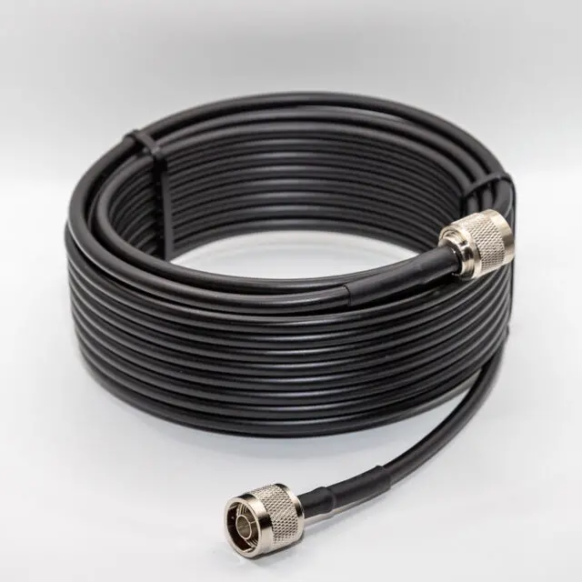
Choosing the right coax cable
Different coaxial cables offer different characteristics when used for an ugly balun:
-
RG-58 – thin, inexpensive, flexible, perfect for 100 W or less.
-
H-155 – similar size to RG-58 but with lower loss, making it popular for portable or QRP operations.
-
RG-8X / LMR-240 – slightly thicker, better power handling, still manageable to wind on 2″ or 3″ forms.
-
RG-213 / LMR-400 – low-loss cables suitable for high-power HF stations, but heavy and harder to wind.
In general, thinner coax is easier to handle and requires less length, but larger coax will perform better at high power and over long service life outdoors.
Selecting a form for winding
The choice of form (the object you wind the coax around) has a significant impact on the resulting choke.
-
PVC pipe – readily available, non-conductive, and robust for permanent installations.
-
Soda or beer cans – cheap and easy to find, good for experiments, though not weatherproof.
-
Plastic buckets or tubing – useful for portable baluns where a larger diameter is desired.
The larger the form diameter, the fewer turns are needed to reach the same impedance. Smaller forms require more turns but result in a more compact choke.
How many turns are needed
The required number of turns depends primarily on the frequency of operation and the form diameter.
-
On 80 m (3.5 MHz), 15–20 turns on a large form may be required.
-
On 40 m (7 MHz), 10–12 turns often suffice.
-
On 20 m (14 MHz), 6–8 turns may already provide excellent suppression.
-
On 10 m and 6 m, only a few turns can result in several kilo-ohms of impedance.
Using the calculator above, you can enter your desired operating frequency, coax type, and form diameter to get an exact recommendation tailored to your situation.
Performance across amateur radio bands
An ugly balun wound for one frequency usually works across a wide range of HF bands, though not equally well.
-
A choke optimized for 20 m often works effectively from 30 m up through 10 m.
-
A choke designed for 40 m tends to give useful suppression from 60 m through 15 m.
-
At very low frequencies like 160 m, even 25 turns on a large form may still not provide enough impedance, so ferrite-based solutions are preferred.
This broad usefulness makes ugly baluns especially popular for multiband dipoles, off-center-fed dipoles, end-fed half-wave antennas, and verticals.
Advantages and disadvantages
Advantages:
-
Very low cost – requires only coax and a simple form
-
Easy to build with hand tools
-
No ferrite cores needed, so it can handle high power without core saturation
-
Works well across multiple HF bands
Disadvantages:
-
Bulky and sometimes heavy, especially with large coax
-
Less effective at very low frequencies (160 m, 80 m) unless many turns are used
-
Performance can vary due to turn spacing and self-capacitance
Practical building tips
-
Use UV-stable coax for outdoor installations to ensure long life.
-
Keep the turns tight and evenly spaced to maximize inductance.
-
Secure with tape or zip ties to prevent shifting over time.
-
Mount away from metal surfaces to avoid detuning.
-
Weatherproof thoroughly if used outdoors to protect the coax jacket from sun and rain.
Comparing ugly baluns with ferrite chokes
While ugly baluns are popular, ferrite-based chokes are also widely used. Each has its place:
-
Ugly balun: Cheap, robust, handles high power, great for portable or budget builds.
-
Ferrite choke: More compact, predictable performance across a wide frequency range, better suppression on low bands.
Many operators use both: a ferrite choke near the shack entrance, and an ugly balun at the feedpoint, combining the strengths of each approach.
Applications in amateur radio
You can use an ugly balun in many situations, such as:
-
At the feedpoint of a dipole or vertical antenna
-
On the coax of an end-fed antenna to reduce RF feedback
-
Near the radio equipment to prevent RF entering the shack
-
As part of portable field operations, since it can be wound quickly with spare coax
The ugly balun is one of the most accessible and practical RF suppression tools available to ham radio operators. It doesn’t require expensive materials, it can be built in less than an hour, and it significantly improves station performance.
By using the calculator provided above, you can accurately determine the number of turns, the length of coax required, and the expected effectiveness across all major HF bands. Whether you are a new ham experimenting with your first dipole, or an experienced DXer building a contest station, adding an ugly balun is a small step that delivers big benefits.